If you’re responsible for sourcing a new purified water system or are responsible for an existing system, it’s important that you understand what a purified water system does and how the different components work together. This article will provide you with an overview of the most common variations of reverse osmosis (RO) based water purification systems for pharmaceutical applications.
General Process Flow
The US Pharmacopeia (and others) specify that purified water must be produced from potable water. For simplification, we will assume here that the purified water system is fed from a municipal potable water source.
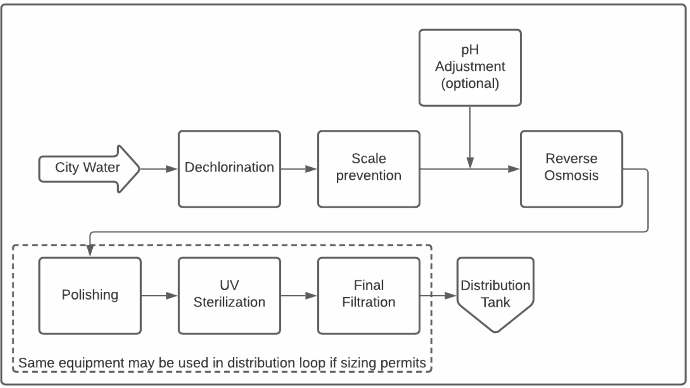
Pharmaceutical Purified Water Production System Diagrams
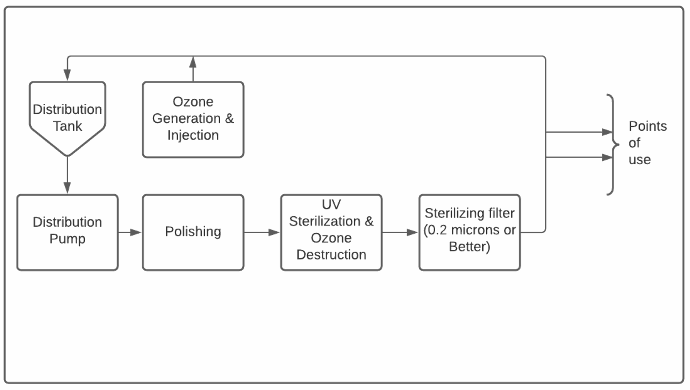
The diagrams below illustrate the typical major components of pharmaceutical purified water production and distribution systems. Keep reading for a detailed explanation of each unit operation.

Typical Purified Water Distribution Loop

Reverse Osmosis – The Heart of the System
At the heart of almost all modern purified water systems is a reverse osmosis (RO) machine. Reverse osmosis is a process for removing dissolved impurities from water by forcing water through a semipermeable membrane. The water is stripped of most of its contaminants as it passes through (permeates) the membrane. This purified water is commonly called RO permeate.
Not all the water passes through the membrane, though. Some water remains on the “dirty” side of the membrane and helps to flush contaminants away from the membrane’s surface. In order to prevent the membrane clogging, two conditions must be met:
- The contaminants must be kept in solution; and
- The contaminants must be swept away by the water, meaning that the “cross-flow” must be maintained to promote appropriate turbulence and velocities at the membrane surface.
A reverse osmosis system typically sends about 25% of its feed water to drain. This means that 4 gallons of feed water are needed to produce 3 gallons of RO permeate. This 3:4 ratio means that the system is operating at 75% recovery. System recovery rates are limited by RO design choices and operating conditions.
Pre-Treatment: Keeping the Heart Beating
The performance of RO machines degrades under the following conditions:
- Inorganic fouling of the membrane surface, also known as scale;
- Organic fouling of the membrane surface;
- Biological fouling of the membrane surface and flow channels;
- Membrane oxidation;
- Obstruction of flow by sediment or other suspended solids; and
- The scale prevention step prevents inorganic fouling, which is typically caused by hardness or metals. These contaminants precipitate when their concentrations exceed solubility limits, covering portions of the membrane with scale.
The scale prevention step prevents inorganic fouling, which is typically caused by hardness or metals. These contaminants precipitate when their concentrations exceed solubility limits, covering portions of the membrane with scale.
Organic fouling is caused by the presence of organic compounds in the feed water. It is sometimes prevented by a separate organic removal pre-treatment step and other times handled by carrying out periodic high pH cleanings of the RO system. Adequate cross-flow and lower membrane flux rates can also contribute to mitigation when operating the system in adverse conditions.
Biological fouling occurs when bacteria cover a significant portion of the membrane surface with biofilm. This growth inhibits flow through the membrane as well as inhibiting the very important cross-flow that keeps the membrane surface clean, a double whammy that negatively impacts the quantity of water produced as well as its quality. Biological fouling can be slowed by upstream disinfection and by maintaining some dissolved oxygen in the feed water. Pharmaceutical RO systems are typically designed to be sanitized chemically or with hot water on a regular basis in order to limit bacterial growth.
Membrane oxidation is fast, irreversible and is caused by the presence of oxidants in the feed water, such as chlorine, chloramines or ozone. Most purified water systems include a dechlorination step as most municipal water supplies provide water with either a chlorine or chloramine residual. Aging and chemical exposure have a similar but much slower effect.
Sediment and other suspended solids physically “plug up” the RO membranes in a system. This leads to reduced and uneven flow through the membrane elements, increasing the rate of fouling, decreasing water production and eventually decreasing purified water quality.
Polishing
In most cases, the permeate from an RO machine is not quite pure enough to meet pharmacopoeia standards, most notably with respect to dissolved solids. The polishing step further removes dissolved ions and organics so as to reliably meet conductivity and total organic carbon (TOC) limits. This is typically achieved with ion exchange but can sometimes be achieved with a second RO purification step.
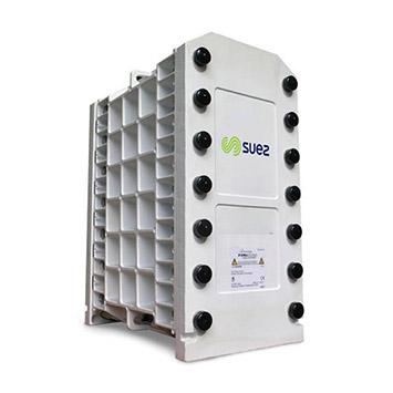
Heat sterilizable EDI system installed on a purified water production system

Distribution
Purified water does not stay pure for very long. After all, water is the universal solvent as well as the basis of life as we know it! Purified water distribution systems are most often designed as loops where the purified water is stored in a sanitary tank and is pumped around a loop with one or more on-demand usage points.
While distribution loop designs vary, it is widely accepted that they should maintain a minimum water velocity and contain no dead volumes – areas where water can stagnate outside the main flow.
Water flowing through the distribution loop sometimes flows back through the polishing step so as to keep it purified since the air in the storage tank causes an increase in conductivity as CO2 dissolves into the water.
Sterilization
The final step in producing purified water is sterilization. This step is generally integrated into the distribution loop. While many approaches exist, almost all systems include a final filtration step with 0.2 or 0.1 micron cartridge filters providing a final physical barrier against bacteria.
Additionally, many systems include an ozonation system to maintain low levels of ozone in the distribution tank and, sometimes, to allow for a periodic ozone sterilization of the distribution loop itself.
Finally, ultraviolet (UV) sterilization units are often used for sterilization and, sometimes, for TOC reduction. It is generally recommended that these units be installed upstream of the final filter so that any dead or deactivated bacteria will be caught by the filter. UV is also used to break down ozone since compendial waters must not contain ozone at the point of use.
Conclusion
Vous avez des questions sur le fonctionnement des systèmes de purification d’eau pharmaceutiques? Contactez-nous ou laissez un commentaire ci-dessous. Nous aimerions recevoir de vos nouvelles!